Have you ever thrown a shopping cart out of a convertible at 80 mph to observe the sparks? How about hooking up a power amplifier to 115 volts AC just to see how it craters? Your fellow engineers have done these things and more! If you have a great picture of totally destroyed hardware, or a photo of a blown circuit, send it to This email address is being protected from spambots. . If it gets on the web site you will receive a free Microwaves101 key chain pocket knife! Impress your friends, if not your boss!
Note to mortuary contributors: please consider that your boss may not find your submission in the best interests of your Big Company. Lately we've been getting a lot of "please remove my submission" emails, try not to send us anything that you might regret.
Note to Big Companies: Don't blame us for posting your spectacular failures, we only post what your employees send us. On the other hand, please don't rip off Microwaves101 pictures for presentations without permission, that's bad manners. Maybe it's time for some training!
Note to mortuary fans: We put new stuff here at the top, but older disasters are still here too--just scroll down.In many cases, if you click on pictures on this page you can see higher resolution images.
This story came from Chris. This story is about a 76 lbs., $8K antenna being shipped in a cardboard box marked "fragile". By not protecting the antenna during shipping, the supplier might sell two each time, one to the insurance company...
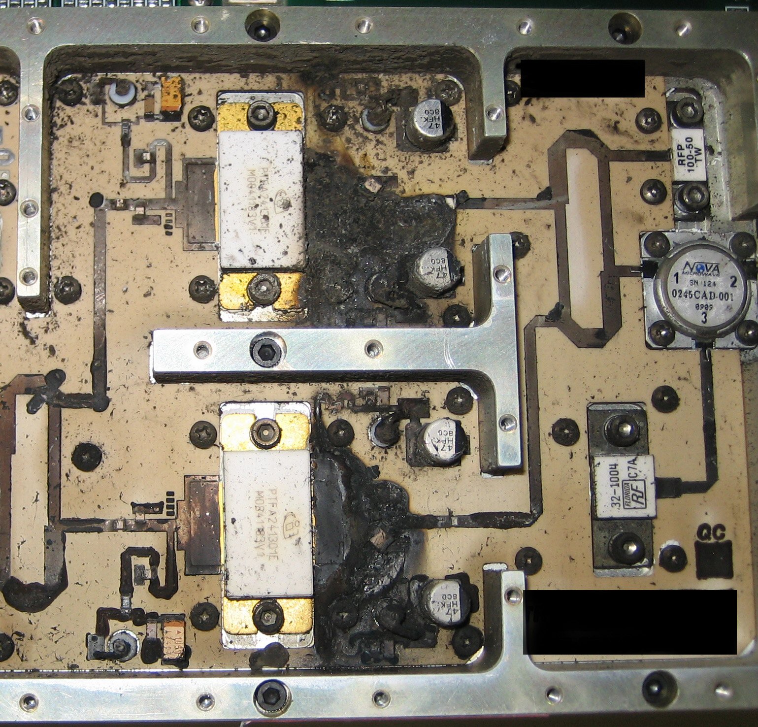
This image is thanks to Dean:
Please see attached a nice photo of an obliterated 200W 2.4 GHz SSPA output section. This was a customer return, no ideas yet on how this happened. We’ve seen similar damage to PAs in transmitters that have had lightning strike them (with no arrester on the output).
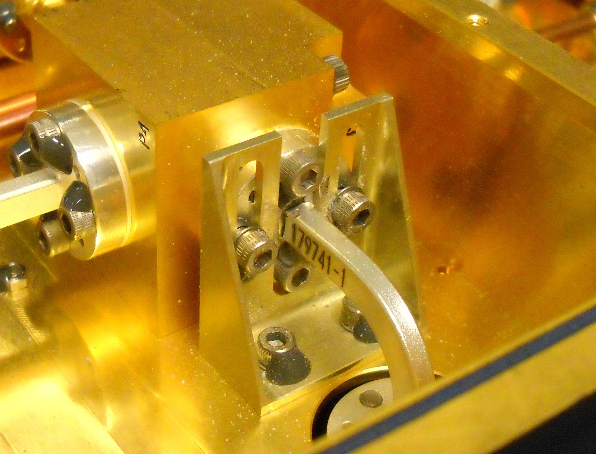
This image came from Happy Trails, who previously contributed photos of waveguide windows being blown and Technicolor circulators (scroll down to find them). Thanks again!
Here is a pic of WR10 waveguide that did not survive the vibration test. This unit was tested for three months and then it failed vibe, meaning three months of constant testing are now null and void.
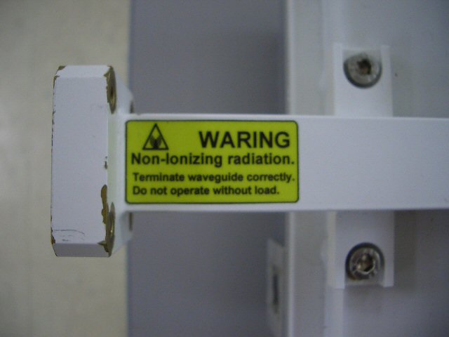
This photo came thanks to Will from Down Under. We had to read it carefully to see what the problem is. That's why we don't work in QC!
Attached is a photo of the output waveguide one of my company's 25w Ku band BUC's*... someone in production must have been taking a nap when this thing was built! Thankfully the labels come from a vendor so this particular idiot isn't ours, but our idiot is just as bad for putting the label on!
*Block Up Converter, used in microwave satellite communications equipment.. it's like a mixer and a high power amplifier all in one. Takes a (in our case) L band IF at low power, mixes it up and amplifies it at the dish so the feedline loss is nice and low.
These pictures came from Tk, who deserves a MacGyver Award for his efforts:
The attached pics speak for themselves. What you see here represents ~60-65 dB of attenuation. My digital radio source was ~+22 dB, patch cables -1 dB each.
Where does all the non-transferred power go? Probably back to the source! Good thing we've got some solid output gain stages!
Here's some more images from Tk that we didn't get around to shrinking: 1, 2, 3, 4, 5, 6
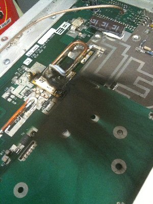
These came from Matthew (thanks!)
Attached are two photos of what happens when the laser used to hermetically seal the aluminum housing of this RF assembly is turned up to “11”.
It blasted through two covers and a gasket to vaporize a portion of the RF circuit.
This photo is thanks to Jim!
LDMOS power amp gives up the ghost.
My co-worker and I went to change the PA tube in our FM Broadcast transmitter. We switched on the solid-state auxiliary transmitter and powered down the main. After installing the new tube, it arced the first time the HV was turned on, causing a brief power outage. We then smelled something burning. After, disassembling the tube transmitter expecting to find burned parts, we found nothing. Then I sniffed the exhaust air from the auxiliary transmitter. I told my co-worker, "I don't think it's supposed to do that!"
New for May 2010! These came from Ed, thanks!
Here is a picture a piece of 12’" C-band flexible waveguide. This waveguide is in the bottom of our pedestal/antenna assembly. It is located below our azimuth rotary joint. The rotary joint seized and caused the flex waveguide to then become the rotary joint…… momentarily!
Ironically, we were still getting returns from this setup! Albeit, about the range on the radar display was 3 miles as opposed to the 300 that they were accustomed to. I changed the flex and all was good again. I love simple problems like this one!
These pictures came from Peter, way back in January, and fell through that crack in the Microwaves101 floor. Sorry for the delay, and many thanks, sir!
The first picture shows connectors from a 10 kW switch that suffered badly. What happened was during a high power transmit period a small piece of metal broke off inside the relay, starting a fire inside. The result is a totally burned relay. Second picture shows the 7/16 DIN coax connector that lost the center pin and the teflon insulator in that same burn. The relay has been repaired and is now in service again in my 144 MHz Earth Moon Earth (EME) station.
These came from David, who offers this simple explanation:
Someone took the back feet off a Tektronix scope and then used too-long screws to put the scope back together. And then sent it to our Calibration Lab to be calibrated.
Bummer! The perpetrator deserves to be promoted to manager so he/she can't do any more damage...
These came from Colin, who had a little problem with heat. Come to think of it, without heat, this mortuary would be significantly reduced in scope...
I thought I'd share a couple pix taken of a voltage regulator that was dissipating a few more watts - into the highly ineffective circuit board instead of a heatsink. There was a 5A fused "protection circuit" that failed to blow the fuse, and of course, it didn't protect the regulator, or anything downstream. A 12V supply was feeding about 4A to equipment under microprocessor control, and a single fuse was used for the load as well as the 5V logic - so when the logic failed and drew about an amp, that was still fine with the fuse (4A + 1A = 5A) but the regulator was now dissipating 12-5=7V * 1A = 7W - without a heatsink. The microprocessor normally drew a few milliamps.
You can thank John for these SEM images. They are very high-resolution, be sure to click on them to see destruction at the micron level!
Thought I'd send along a couple of pix of deceased IC's I took at work on our scanning electron microscope.
The first image is of an IC that had way too much current passed through it. We expected to see just the usual destroyed substrate but instead were surprised to see this nice little fiber of silicon oxide that grew out the unfortunate device. The device became hot enough to actually oxidize the silicon and cause the fiber to grow instead of just explode. Shades of the movie "Alien".
The second image shows a semiconductor from a power supply that we "unfortunately" managed to destroy by accident one day in the lab. We decided to cut open the deceased part to have a look. Not much left of it here, just this destroyed micro landscape. As I recall the part was something like a voltage regulator IC in a TO-3 package.
This picture came from Mario, and illustrates what can go wrong when you don't "match the load to the generator..." Thanks! Hopefully we can all stay friends!
While on vacation in Europe a friend of mine plugged my battery charger into an outlet using an adapter but no transformer. Apparently 220V was more than the poor charger could take. After hearing a loud pop and opening the charger up, the damage was obvious. What wasn't as immediately obvious was the damage done to the house's electrical system...
New for January 2010! These images came from Karol, in Gdansk. Nice Christmas colors!
I'm an Electronics student from Poland and I have a few pics for your mortuary - please see the attached files.
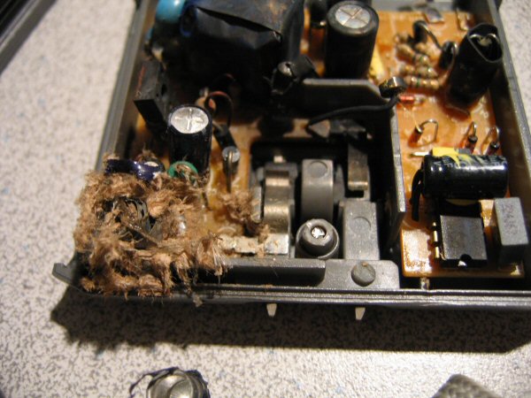
The first one is a cratered FPGA chip. It was some kind of measurement equipment and this damage is caused by a thunder storm. The second picture shows a few other chips on the same PCB as the xilinx chip. In the blue circle you can see a laser burn on the CCD sensor of my camera :( Be careful when taking pictures of working lasers. On the third and fourth photos you can see a power supply module from the same equipment.
Fifth and sixth picture shows a self made probe for measuring something on a 3-phase power line. The resistors got hot and melted the caps. It was a design fail because that kind of resistors are supposed to get hot. It's quite surprising that the caps still work (I mean there's no short or open circuit and they still act as a capacitor).
The last picture shows a blown IGBT brick. I got it from trash so I don't know what has happened to it.
Thanks, and sorry for the delay caused by our overflowing spam bucket! - UE
Need more Microwave Mortuary? Check out our archives!