
Have you ever thrown a shopping cart out of a convertible at 80 mph to observe the sparks? How about hooking up a power amplifier to 115 volts AC just to see how it craters? Your fellow engineers have done these things and more! If you have a great picture of totally destroyed hardware, or a photo of a blown circuit, send it to us! If it gets on the web site you will receive a free Microwaves101 key chain pocket knife! Impress your friends, if not your boss!
Note to mortuary contributors: please consider that your boss may not find your submission in the best interests of your Big Company. Lately we've been getting a lot of "please remove my submission" emails, try not to send us anything that you might regret.
Note to Big Companies: Don't blame us for posting your spectacular failures, we only post what your employees send us. On the other hand, please don't rip off Microwaves101 pictures for presentations without permission, that's bad manners. Maybe it's time for some training!
Note to mortuary fans: We put new stuff here at the top, but older disasters are still here too--just scroll down.In many cases, if you click on pictures on this page you can see higher resolution images.
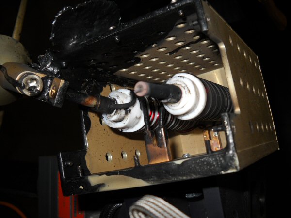
December 2011: A reader sent in this:
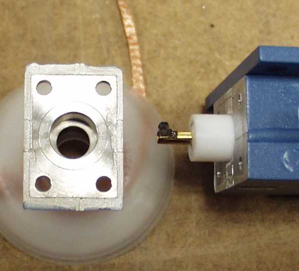
What happens when a power bicon antenna fails during EMI immunity testing? Well, it depends. This model was rated at 3500W CW. Something failed while running only 1000W CW. The delrin insert in the end actually caught fire and completely melted. This started a whole chain of events, including several frantic emails to the vendor to get MSDS sheets to find out what possible issues could arise after the fire was put out. By the way.. Delrin and Teflon (both trademarks of DuPont) burn with a CLEAR flame... luckily, we're retiring this style of antenna for the frequency range and field requirement in question.
New for November 2011! This information came from Vern, who send us a pdf document entitled Vomit Fried Amplifier:
I've been meaning to send this in for quite some time, but never seemed to think of it when I had a few minutes! One of my cats had taken to sleeping on top of my stereo amplifier, evidently for quite some time! One day he lost his cookies right down the vents in the top cover. I was able to repair it though!
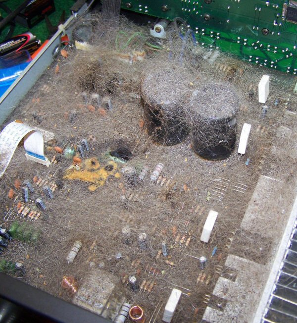
Download Vern's entire Vomit Fried Amplifier pdf document here.
Also new for November 2011, this came from David:
Phone call last week from satellite truck operator to engineer: "I can't see my return from the satellite and my HPA keeps tripping OFF with a 'high reflected" fault. What do you think is going on?"
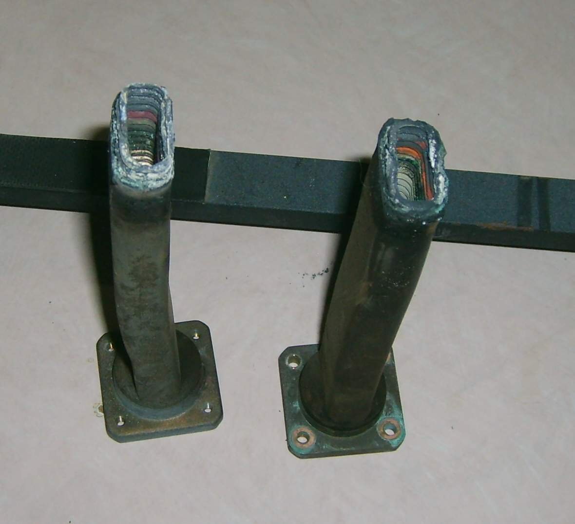
We added David's image to a new page on flexible waveguide.
New for October 2011! These came in from Dave in the UK:
A couple of suitable anonymous "mortuary" items attached.
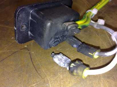
Both were from the same repair job, a high power low band microwave amp, that "had just stopped working". The burnt N on the directional coupler, the customer didn't know about, which we find surprising as that RF connector was visible when they took the interconnecting cable off. Interestingly, they did say they had junked a few cables recently, both RF and AC power!
We just fix'em, we don't design them, but you have to wonder about using automotive type crimps on the back of 240V 16A IEC connectors. At least the safety ground was soldered... We fitted something larger and much more capable, with full agreement of both the customer, and equipment supplier. The needed new directional coupler, was "very" expensive. No more "events" like this have been reported. I suspect the RF cable was not correctly fitted.
New for July 2011! These came from Robert from Down Under who offers a lesson in Myrmecology:
We left an HP8648C signal source a little too long in a cabinet in our outdoor antenna range, and discovered that there was no RF output . . . thanks to a colony of ants which took up residence.
This is what the step attenuator looked like after disassembly. I have no idea how the ants got in there. But that's not all. Most of them had congregated in the synthesizer board (a nice warm oscillator!), which was an easy clean-up job in comparison.
Fortunately the Agilent guys had a replacement attenuator in stock.
Thanks!
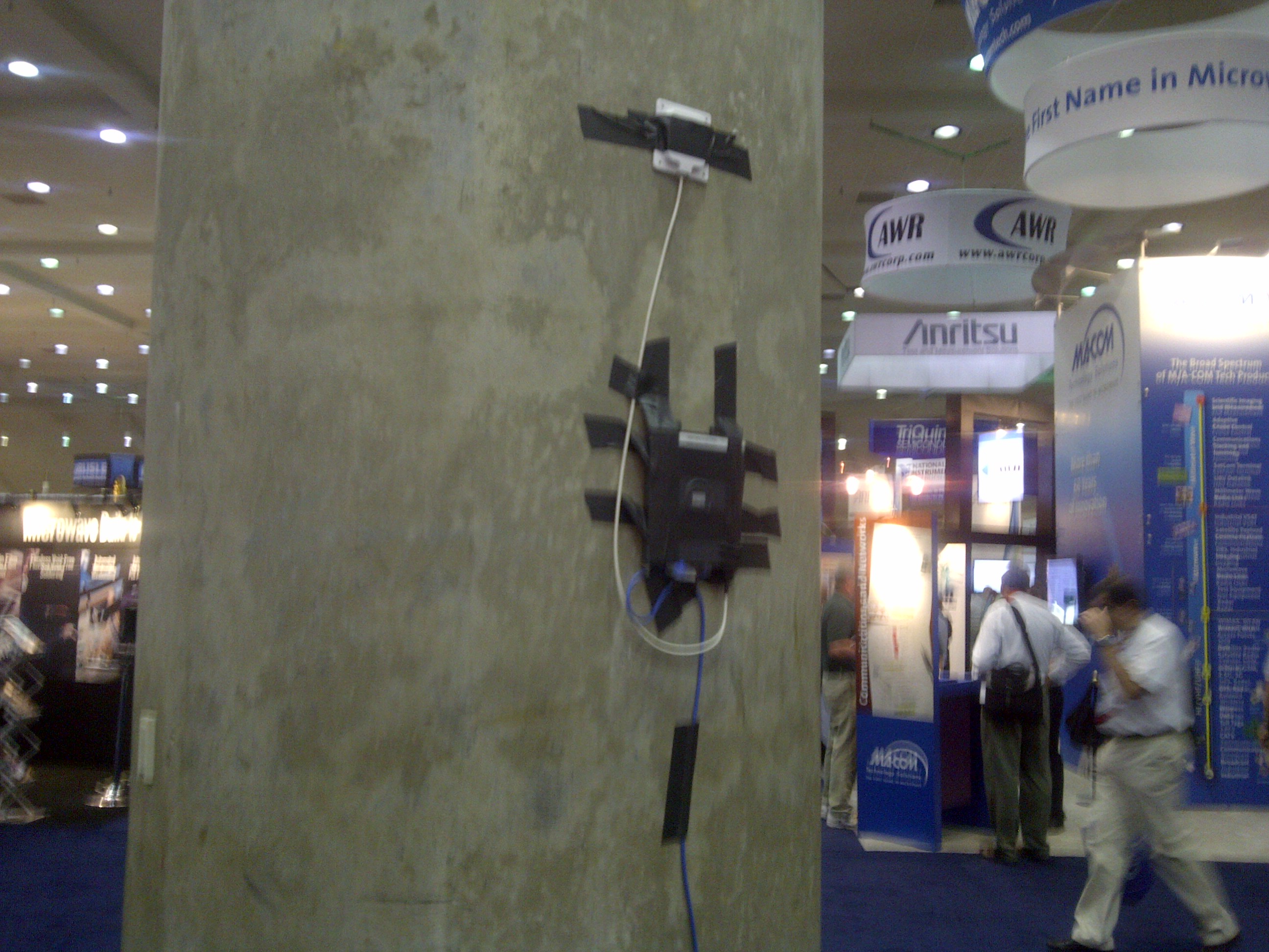
New for June 2010! This photo was taken at the IMS show in Baltimore by John:
In cased you missed it, here should be an award for Best WIFI Install at a Trade Show.
Also new for June 2011! These two photos came from George:
Just to let you know, no black powder was used in the destruction of these electronics, as were the last photos I sent.
I don't know if these are useable, but this is the best shot I could get of the filter/protection section of a RTU (Remote terminal unit, yet another TLA! HA!) , before the technician who blew the thing up (during training, thankfully) tried ripping the camera away from me. I hope you can use them.
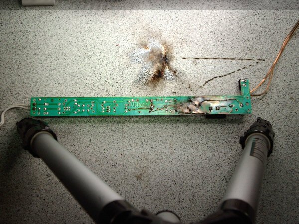
New for May 2010! This image came from Spiros, who offered this Mortuary Recipe:
Title : PCB Annihilation
Subject Under Test: Compact Fluorescent Lamp Control Board
Test Voltage: 240 VAC
Current Passed Before the Big Bang: ~ 20A
Test Results: PCB Annihilation. Cu, Pb, and other substrate moved in on the lab bench on a permanent base.
Story Moral: Check for shorted rectifier diodes if you do not want to trigger an explosion in the lab.
New for April 2011! These images came from Chris.
Our Doppler radar is a 5(ish) GHz 350KW (2.5 MW ERP) unit located on some leased land on a farmer's property. This farmer called one of our engineers to say that the loud buzzing from our radar site was keeping him from sleeping.
See the pictures for the damage caused by the all the RF splattering around inside the unit due to the twist flex failure. The heat caused the bearings in the rotary joint to fail as well. Failure was likely caused by moisture ingress due to a waveguide leak that overwhelmed the desiccant in our compressor dryer.
Also new for April 2011! These images came from Ashley, who knows her ophiology as well as her heliax!
Don't cut the wrong cable!
Actually, don't cut any cable ! Don't put your hands in there. The snake is an Australian Eastern Brown snake. I'd been working on replacing feeders in this tray for a few minutes before I noticed the brown heliax! I didn't get bitten, though I'm not sure how. These snakes are known for being aggressive especially when cornered.
New for February 2011. This came from Paul...
I have some images for you! Exotic, exciting images of a 500MHz superconducting cavity failure. As the pictures show, the cavity is fed with a waveguide. During assembly, the outer helium vessel is pressurized to 12 psi while in the internal RF volume is under a 10-7 Torr vacuum. Well, if you look closely, you'll notice that the waveguide couldn't handle the load.
In subsequent designs, the wall thickness was bumped up from 3mm to 4mm.
Also new for February 2011. This from David:
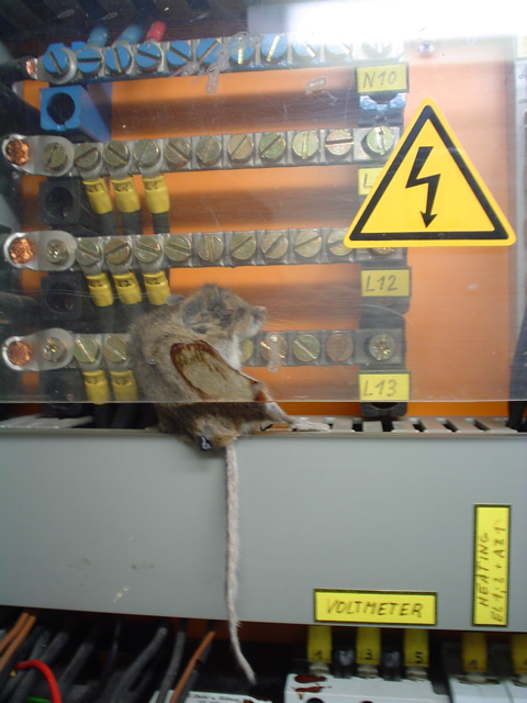
This happened when a small furry friend forgot to lock out the equipment, ignored the big warning label, and walked behind the Lexan guard over the 480V junction block in the antenna servo control box at the Submillimeter Telescope on Mt. Graham in Arizona.
This photo was taken 5 years ago. He's still in there to this day, to serve as a warning to other rodents.
Here is a shameless plug for do it yourself pest control...
New for January 2011! These photos came from Hank. Be sure to click on them, these are some high resolution disasters!
Here are a couple of RF disasters I've had fun reminiscing about for years now, and I think you and your readers might enjoy them too.....
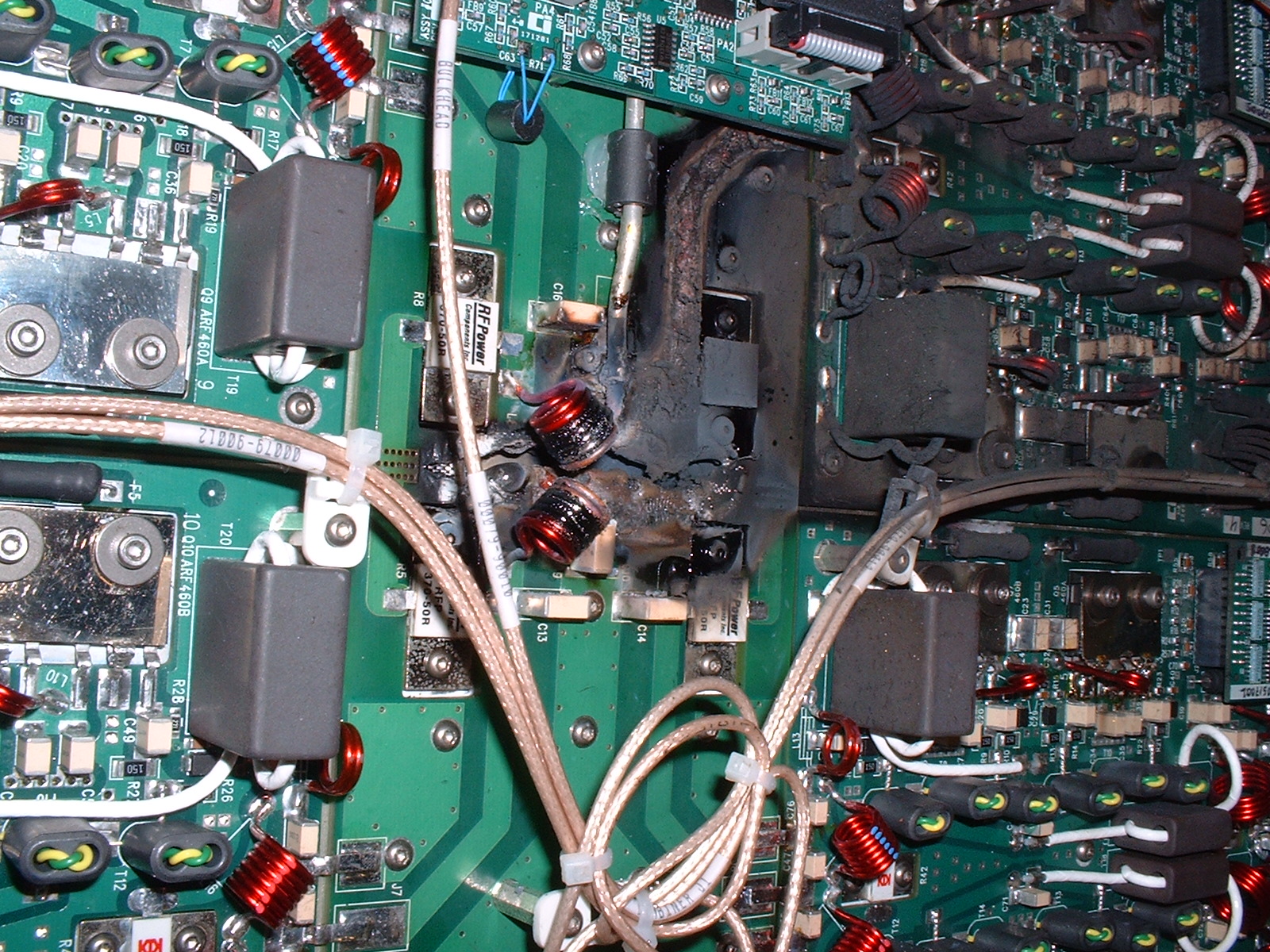
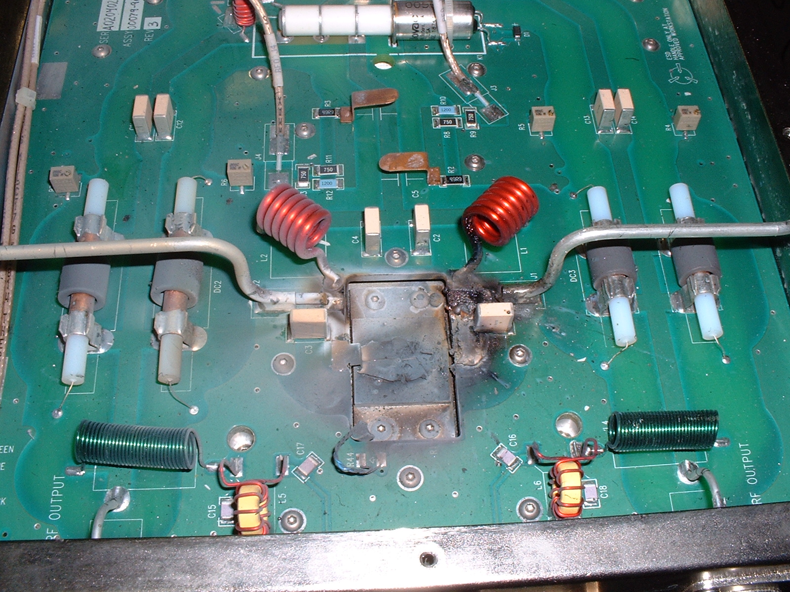
The first pictures are of a "situation" that happened to a couple of lumped element Wilkinson power combiners in an MRI amplifier. I was working at this company doing the PA design, and one of my co-workers was in charge of torture-testing the amp. For some reason he decided to run it for an extended period of time with all fault protection circuits disabled, and this was the result. As near as we could tell, something in one of the combiner networks detonated or arced, and the amp just kept hammering away into it until someone shut it off. That's an 800 watt dump resistor that's cratered! Nice!
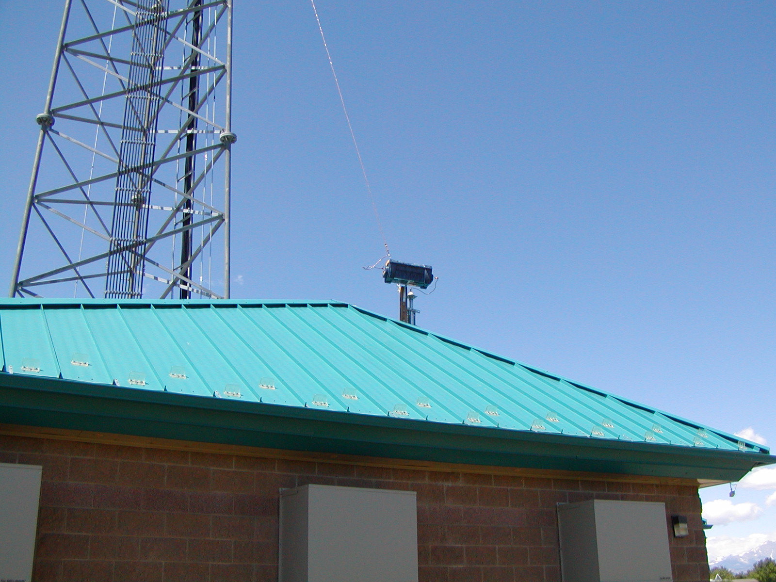
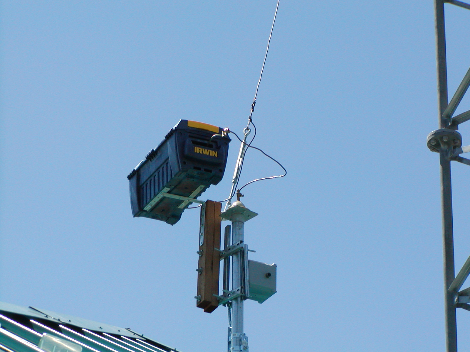
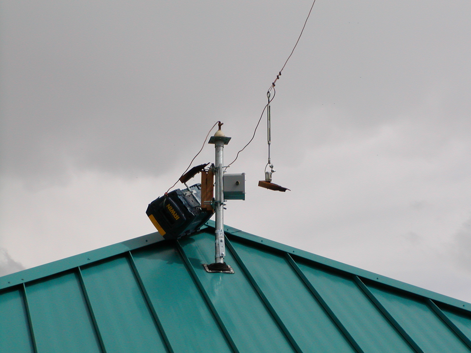
The next three pictures are, believe it or not, a matching network for a 2.5kW AM broadcast transmitter. The transmitter is co-located at a cell site, and the 190 foot tower is shunt-fed via this matching circuit and the feed wire sloping up to a tap point on the grounded tower. The chief engineer at the station decided that a plastic toolbox mounted on a wood insulator would be an ideal solution. When I saw what he did, I knew I had to run home quick and get my camera to take the "before" picture. A couple days later I had to do it again for after pictures! It looks like there's only about a half-inch gap across the wood between the "hot" bracket and a grounded bolt, not a lot even if wood was a good insulator. Evidently, enough of a fire resulted to burn through both 2x4s!
 |
 |
This space is for rent, inquire within... |
 |
 |
 |
Check out our mortuary archive for more!